Estimation of gusts and structural loads for commercial aircraft
International Forum on Aeroelasticity and Structural Dynamics (IFASD) 2009, Seattle, USA, June 21 – 25, 2009
H. Henrichfreise
Cologne University of Applied Sciences, Cologne Laboratory of Mechatronics
50679 Cologne, Germany
e-mail: hermann.henrichfreise@clm-online.de
J. Jusseit
DMecS Development of Mechatronic Systems GmbH & Co. KG
51105 Cologne, Germany
e-mail: juergen.jusseit@dmecs.de
L. Bensch2, L. Merz2 and M. Gojny
Airbus Operations GmbH
21129 Hamburg, Germany
e-mail: marcus.gojny@airbus.com
Abstract
Enhancing the efficiency of aircraft operation is a perpetual objective for every aircraft development. In particular, the monitoring of the system state or condition gained some significance in the past ten years. Considering aircraft in-service support and maintenance scheduling, the diagnosis of the airframe loading yields a very promising perspective. Upcoming customer requests cause new challenges for method development and application within the framework of structural health monitoring. Being linked to signal-based concepts, this key-term is expanded by a model-based set-up. The core of the proposed model-based approach consists of an observer for a non-linear aircraft model with disturbance model to estimate structural loads. The performance of the complete observer set-up is validated by simulation and flight test results, which reveal a promising potential for load diagnosis in fu-ture aircraft application.
1 Introduction
During aircraft operation, forces and moments from aerodynamics, thrust, drag and inertia cause the internal loading of the airframe. They are excited by piloted aircraft motion or by external disturbances, i.e. gust and turbulence. For health monitoring, the structural loads are of interest. Since the system complexity to directly measure structural loads is rather high, a model-based approach is chosen herein, which utilizes aircraft motion measurements and pa-rameters already available onboard of modern commercial aircraft.
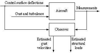
The basic approach is shown in Figure 1. The aircraft motion is affected by control surface deflections and unknown disturbances from gust and turbulence. The measurements consist of aircraft motion variables that are quantified by onboard sensor units. Both control surface deflections and aircraft motion variables are recorded among other operating parameters. All recorded quantities are fed into the observer. Its output is composed of estimated gust veloci-ties and structural loads, which result from manoeuvres and gust. Based on a non-linear air-craft model in the observer and the estimated gust velocities, it is possible to reconstruct loads at any location of the aircraft structure.

Figure 1: Basic approach for estimation of gust velocities and structural loads
This paper is organised in the following manner: Details of the aircraft model are presented in section 2. Section 3 describes the augmentation of the aircraft model and its application to the observer design process. Section 4 presents the performance achieved with the observer concept, which is illustrated with simulation results for gust and turbulence excitation of a commercial aircraft. A brief discussion of results that arise from applying flight test data to the designed observer set-up is also performed in this section. Finally, section 5 gives a summary and an outlook to future work.
2 Non-Linear Aircraft Model
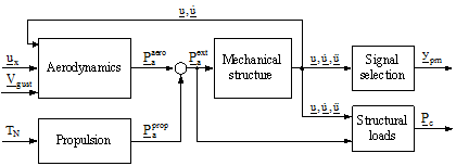
This section briefly introduces the aircraft model used as the basis for the observer design. Its structure and interacting internal quantities are depicted in Figure 2. The aircraft model consists of five sub-models, which are described below.

Figure 2: Structure of the non-linear aircraft model
The sub-model ”Mechanical structure” describes the dynamics of the elastic aircraft structure. It comprises the non-linear equations of motion of the rigid body with all 6 degrees of freedom (DoF) to simulate flight manoeuvres over a broad range of flight conditions and a set of linear differential equations for the elastic motion of the aircraft structure. The latter is extracted from a finite element model with lumped masses. Depending on performance requirements on the model and the capability of the available computer hardware, the number of the elastic DoF can be reduced by means of appropriate order reduction methods. The sum of external forces Paext represents the input to the sub-model, its output u, u', u''comprises the rigid body and elastic aircraft motion variables.
The aerodynamic forces Paaero are set-up in the sub-model ”Aerodynamics”. Optionally, these forces can be based on aerodynamic strip theory or on panel methods [1, 2]. The corresponding aerodynamic influence coefficients are derived from wind tunnel measurements and are validated by flight tests. The forces are computed from the control surface deflections ux, the aircraft motion variables u, u' , and the gust velocities Vgust, which are the sub-model inputs. Of course the aerodynamic model depends on system parameters, e.g. Mach number and air density.
The sub-model ”Propulsion” provides the propulsion forces Paprop. Here, thrust and drag are trimmed with the constant propulsion input TN for a given airspeed and steady 1g level flight.
The measurement variables ypm , e.g. the Euler angles, angular rates, lateral and vertical load factor, are provided by the sub-model ”Signal selection”.
Finally, the internal load quantities Pc at predefined monitoring stations of the aircraft structure are computed in the sub-model ”Structural loads”. Calculating these signals with high accuracy is one of the core objectives of the load estimation concept presented here.
The aircraft model and the simulation environment are described in detail in [3].
The model presented above is the basic plant model for the proposed observer design ap-proach. Its general mathematical set-up is given by the state differential and output equations

The state vector

of the plant model (indexed plant) consists of rigid body and elastic aircraft motion variables.
The deflections of the control surfaces are combined in the control input vector of the plant (indexed plant control)

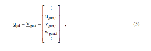
The gust velocities affecting the aircraft are unknown disturbance inputs to the system. They are collected in the disturbance input vector (indexed plant disturbance)

where ugust,i, vgust,i, wgust,i denote the longitudinal, lateral and vertical gust velocities acting at a location i of the aircraft structure. According to Figure 2, the plant output from
...
